Sooner or later every electronics hobbyist will want to build a keyboard. Its a great project that scales from as simple as buying parts and assembling them to as complex as designing your own PCB and case. I’ve been eyeing the Kinesis Advantage 360 Pro for many years, but could never justify the cost. But if I were to design my own, then surely it would be worth it, if only for the experience.
This brought me to the premier open-source bowl keyboard project, the Dactyl Manuform. I customized the design a little, printed high-quality parts, and procured switches and diodes for it. And then I was confronted with the soldering. A common theme in every Dactyl-Manuform build is how annoying the soldering is, and staring down the barrel at over 200 solder joints I decided to look for a better way. After all, what better way to avoid three hours of soldering than to spend three weeks designing a PCB?
The standard build has diodes on every switch and uses the stiffness of the diode legs to provide the structure for the wiring. This is inelegant, and doesn’t support per-key RGB LEDs. I’ve also looked into per-key PCBs and those seem even harder to solder than raw switches and diodes. Flexible PCBs have been tried before, but I couldn’t find any designs that I could easily customize. Naturally, this prompted me to design my own.
Case Design
The essential idea behind this project is to arrange keys in columns of fixed geometry, and to stagger the columns. This allows each column to be internally connected with a flexible PCB, which can be easily manufactured and assembled. The columns are then connected to each other with either a flexible PCB or a ribbon cable. The result is a keyboard that can be assembled with minimal wiring.
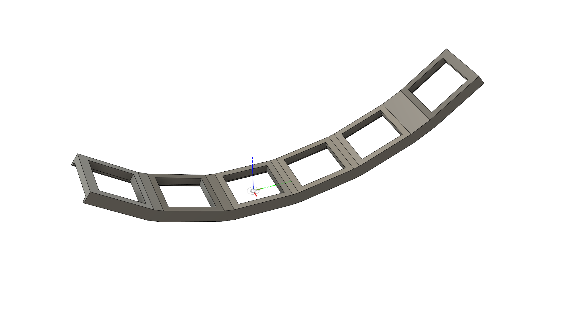
All columns share the same geometry. This is curved inwards, with a little gap for a function key row at the top. This looks like:
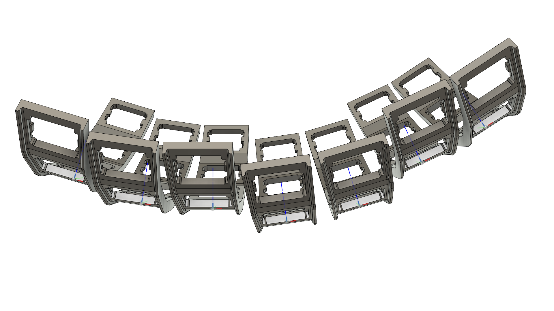
Once we have this, we arrange the columns in a staggered pattern. This works by rotating the columns by a fixed angle about a point far above the keyboard, and then translating each column vertically to give the finger-friendly stagger. This looks like:
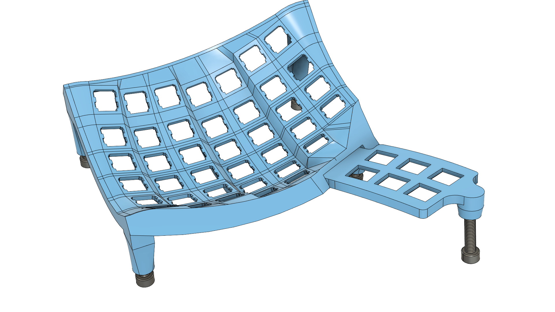
Loft everything, build out a case, and we have a keyboard. This looks like:
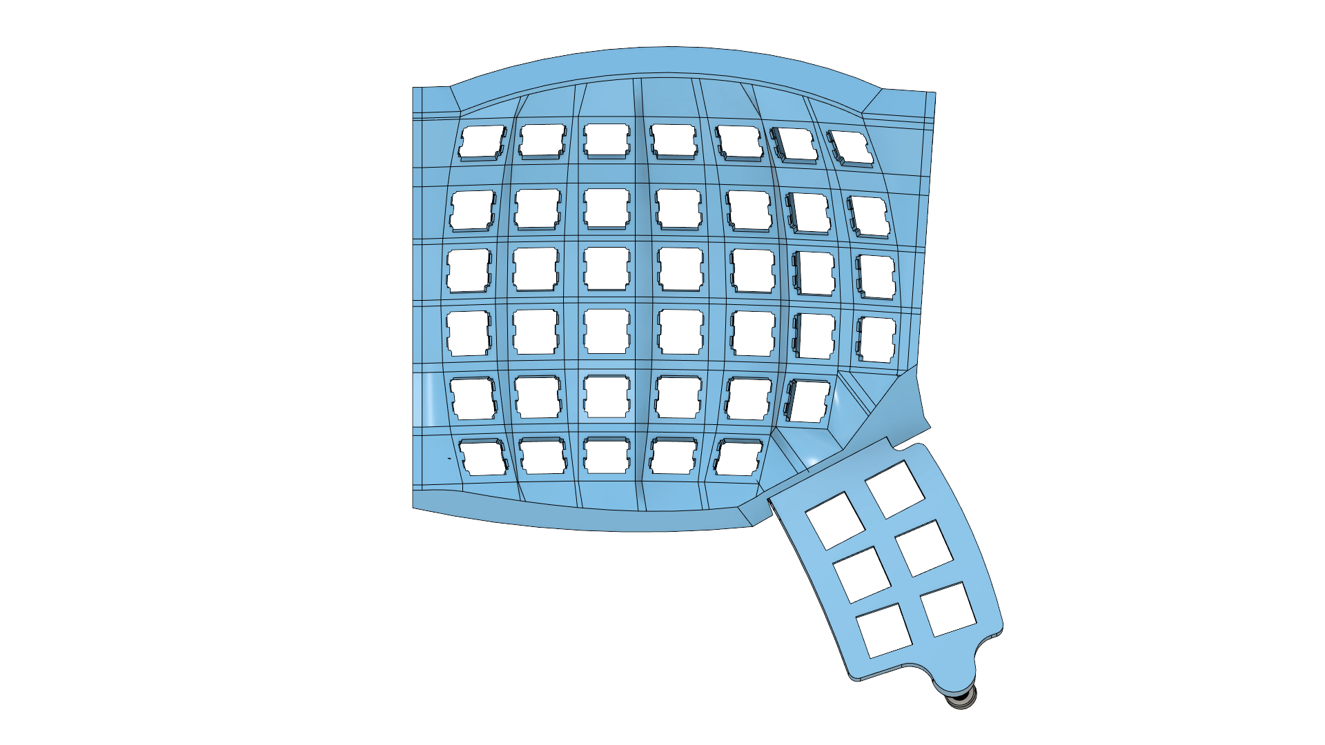
The vertical adjustment is provided by a set of M6 bolts, and the bottom of the case is left open for now.
The PCB
Instead of joining the columns with a ribbon cable, I decided to prototype the design as a single flexible PCB that connects all the columns. This is a little lot more expensive, but it is much easier to assemble. The PCB is designed in EasyEDA (not my usual poison of KiCAD) and looks like this:
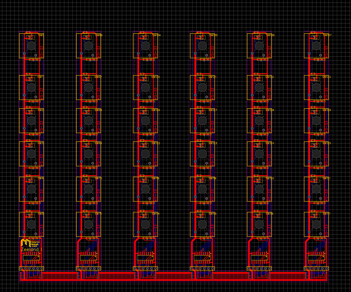
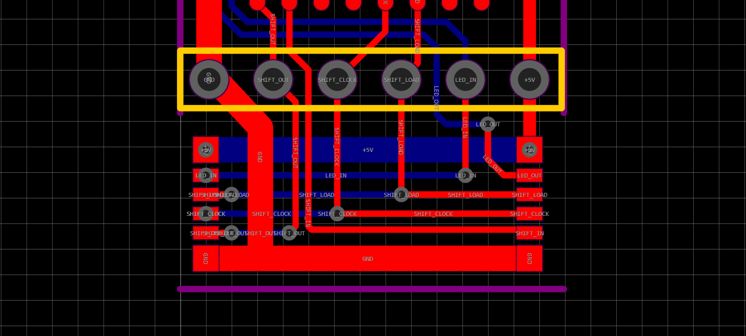
As you can see, the columns are the same, and there is an integrated flexible bus running along the bottom that connects these columns together. Further, the switch states on each column are aggregated by a shift register, and the RGB LED signals are passed backwards using integrated shift registers. Since shift registers are used for both switch and LED signals, an arbitrary number of columns can be chained. The bus is illustrated here:
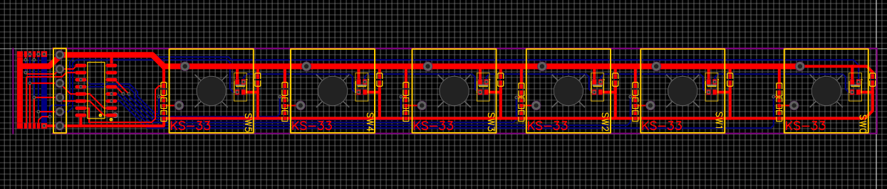
Within each column, the switch states are directly gathered by a shift register, and the RGB LED signals are passed in order from the top of the column to the bottom, with a return line connecting it to the bottom. This looks like:
Per-key debouncing circuit
As the columns are connected through a shift register, we need to debounce the switch signals at the switch instead of at the microcontroller. We do this with a simple RC circuit, following the calculations in this primer by the Ganssle group.
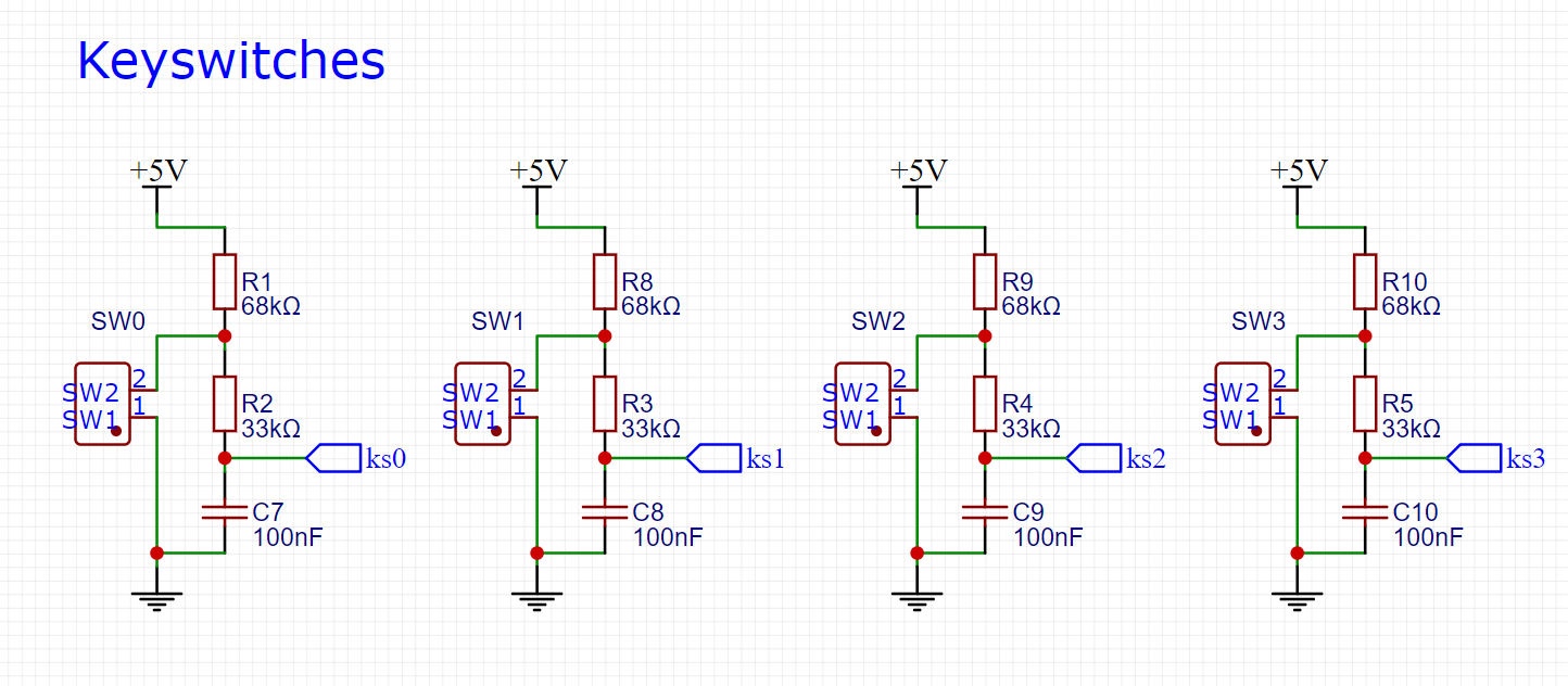
The basic idea is to have a capacitor that you charge and discharge through different resistor paths when you close or open the switch, choosing the capacitance and resistance such that the RC time constant is much longer than the bounce time of the switch. This is a simple low-pass filter, and the output is a clean signal that can be read by the microcontroller.
A test
Even though the price of flex PCBs has come down a lot, these PCBs are not rectangular and so need a custom holding jig to be manufactured. This is the largest driver of cost, contributing about US$110 of the quoted $200 for 10 PCBs. Instead of forking out that much for a prototype, I decided to test the design with a rigid PCB.
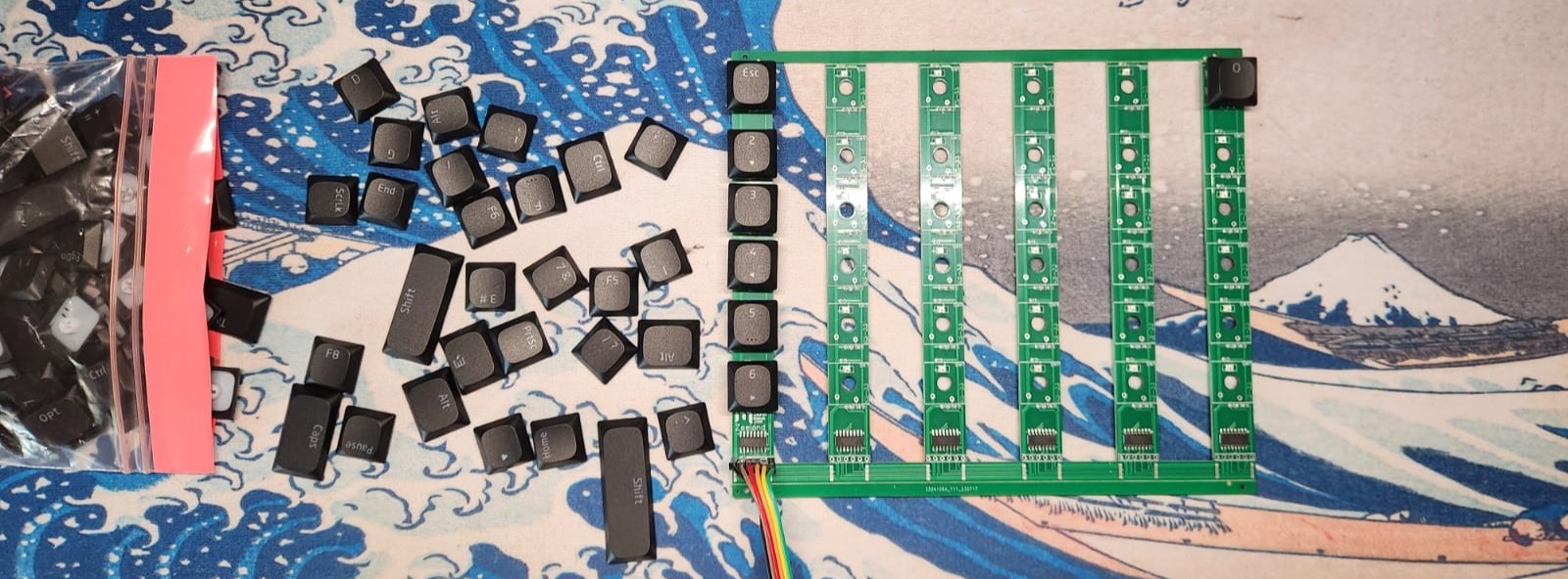
I received it, soldered it up, and the circuit design appears to be sound. I will write up a test firmware and run it on the PCB, firm up the design of the keyboard, and then order a flexible set.