This project makes use of an Arduino and some fairly simple electronics to trigger a DSLR when a person breaks a laser beam. This laser beam is password-protected and can be enabled and disabled using an iPhone/iPod Touch web app. It’s conceptually simple, and makes for really fun party games as well.
The Laser
In my set up, I used several small mirrors to turn the single beam into a grid that covered a room.
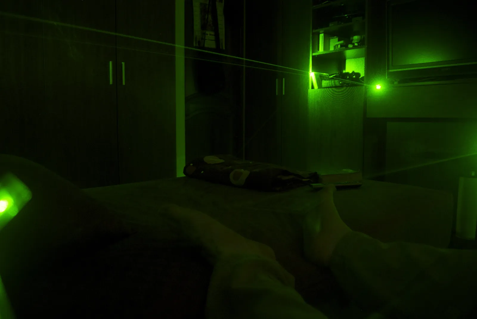
The 5mw green laser is barely visible under normal conditions; the image above has a long exposure timing. The laser is turned on and off by the Arduino, and so this beam is not visible in photos. The laser is from a normal laser pointer, and looks like this:
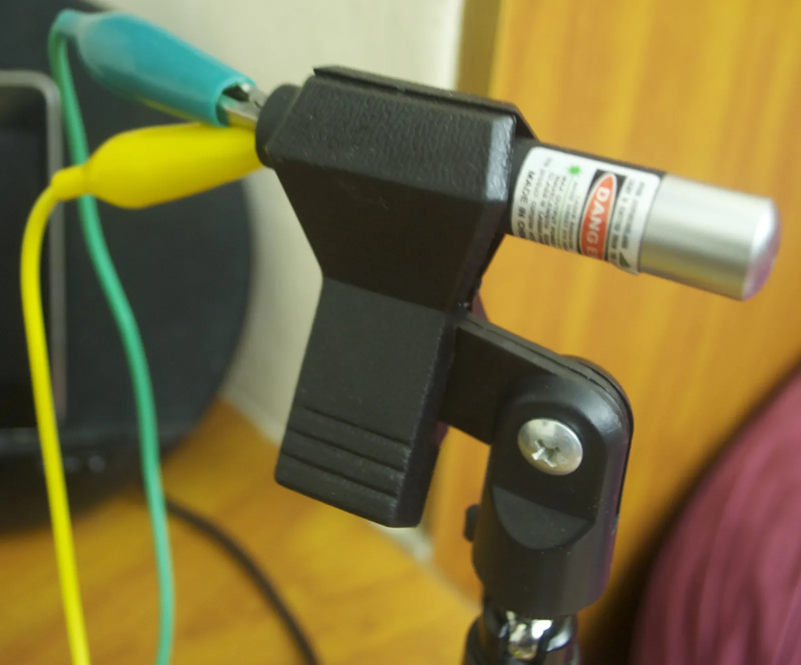
The laser pointer’s button is held down by the clip, and the power supply to the laser is controlled using a relay. The laser beam is detected by an LDR in a simple voltage divider circuit connected to the Arduino. The Arduino is configured to use an interrupt to process the voltage change - this will be described in detail a little further down. As the laser beam is scattered by the imperfections in the mirrors, it is first collected and focused onto the LDR using a fresnel lens. Here is a photo of the beam:
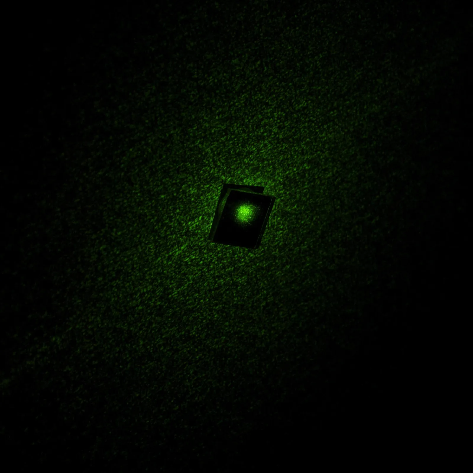
And here is the beam collection set-up:
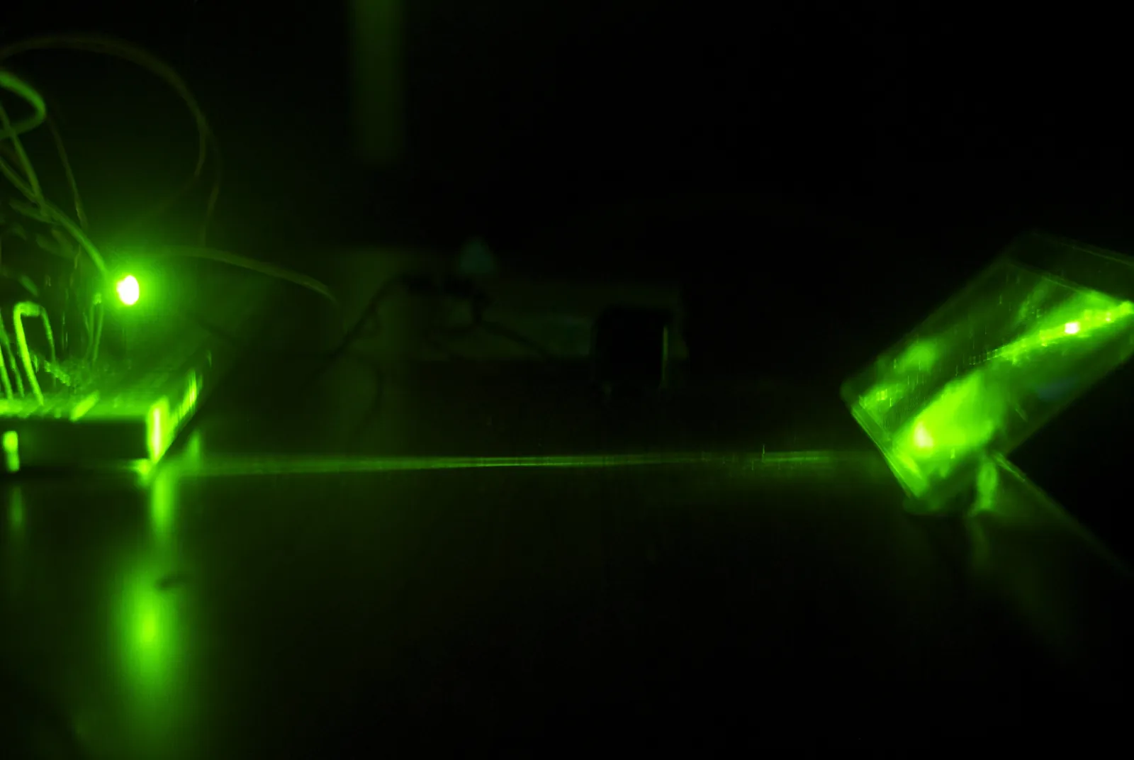
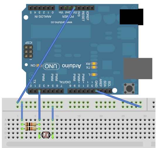
Note the lens on the right. It is positioned to focus the incoming light onto the sensor. This saturates the LDR, allowing it’s resistance to fall to around 300Ω (In complete darkness, it is around 30,000Ω). The circuit diagram is shown below (drawn in fritzing). Note that the LDR is in series with a 5kω of resistance, and that the voltage is being measured by digital input 2, not an analog input.
The simple way of detecting if the light beam was interrupted would be to use the Arduino’s built-in analog to digital converter and the handy analogRead() function to determine the potential across the LDR and use that to calculate the intensity of the incident light. The problem with this is that it’s slow (100μs per read) and it requires constant polling, which prevents it from doing anything else (strictly speaking, this is not true, but at best the polling frequency would suffer.)
By connecting it to digital pin 2, we can use the Arduino’s external interrupt pin to call a function when the voltage rises from LOW to HIGH. Instead of setting a voltage threshold (as we would do in the simple method), we set the sensitivity of the trigger in hardware - by changing the resistance from +5v to the LDR, we can adjust the threshold intensity of light.
The Camera Trigger
The camera trigger is a modified Yongnuo ML-L3 clone (available on eBay) that has additional female header pins soldered onto the button contacts. The remote’s board has holes drilled in a convenient position. Modifying it is simple - just use a screwdriver to pry off the top sticker, solder on the female headers, cut the sticker and paste it back. The original button remains fully functional.
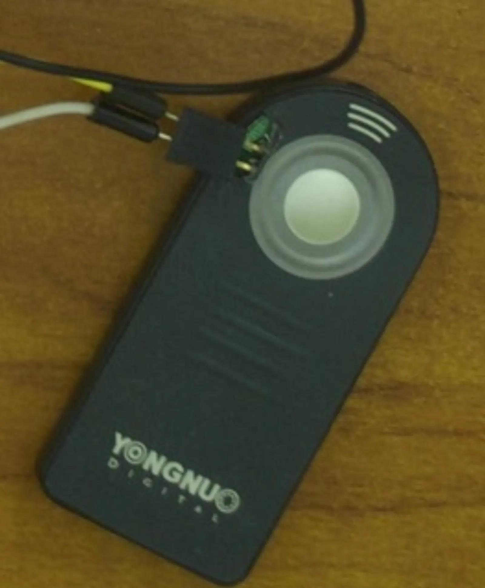
An optoisolator is used (with the two headers connected across the phototransistor end) to trigger the shutter.
The Laser & The Buzzer
Connecting these two is very easy - the buzzer is controlled using a transistor (I used the MPS-2222A, a small NPN transistor), and the laser is controlled using a relay, which is in turn controlled by a transistor.
The only caveat is that the laser diode expects a 3V power supply, and so the relay is connected to the Arduino’s 3V output. Ideally, the laser would have its own power circuit and surge protection and it would be connected to an independent power supply. The photo of the breadboarded circuit may be helpful:
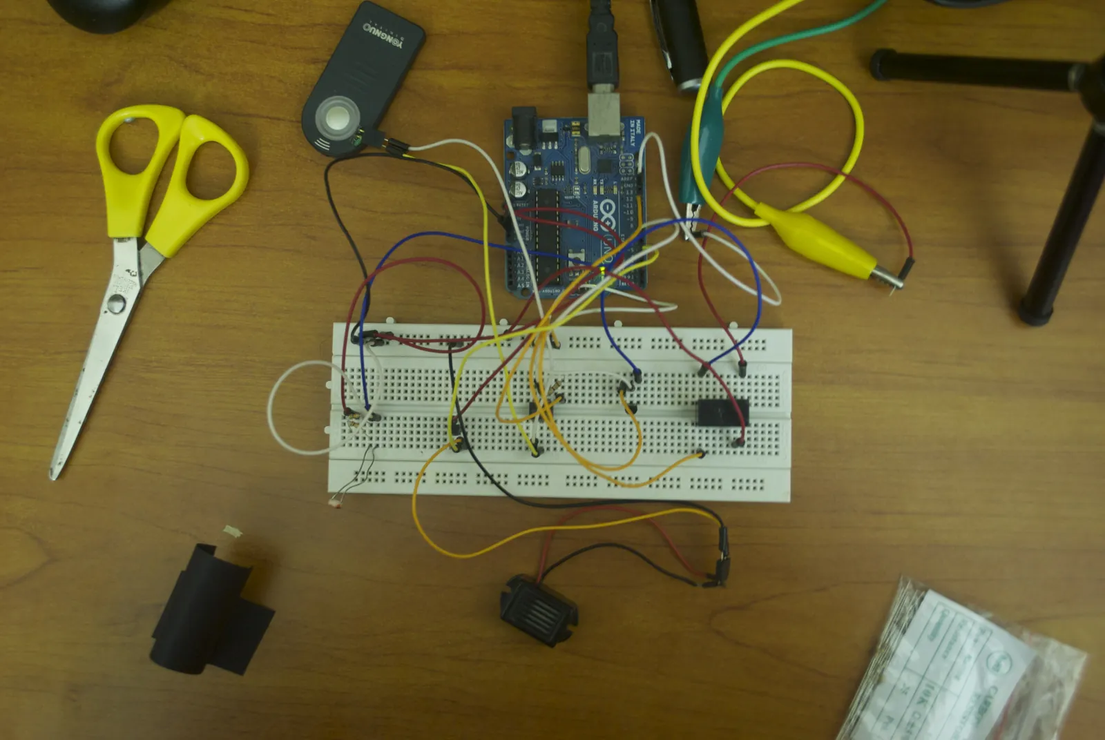
Note the shroud for the LDR on the bottom left of the image. It’s cut from a sheet of black paper, and it allows you to greatly increase the sensitivity of the circuit.
The Code
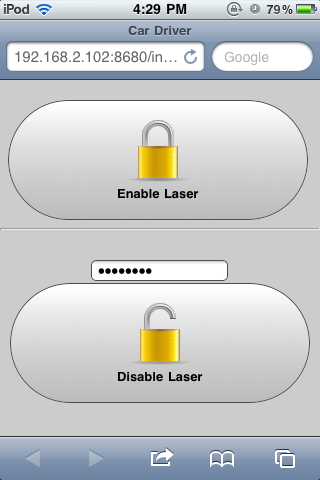
The code is split up into three sections: An iPhone web app, a Python server running on a computer and finally the Arduino code. In the current version of the software, users can enable and disable the laser beam remotely using a very simple interface:
The source code is simple and commented.