You can get the code in this article from this git repository.
So, I received a printer from my grandfather a few years ago. It is a TVS Electronics MSP-145, a clone of (I think) the Epson VP-500 purchased in 1994.
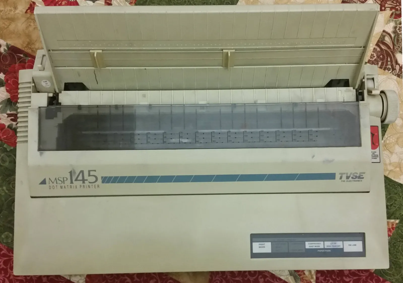
Connecting it to a computer was trivial - a cheap USB-Parallel adapter and Ubuntu automatically recognized the device as a printer. Selecting the “Epson Dot Matrix” driver allowed the printer to produce some nominal output.
The Manual
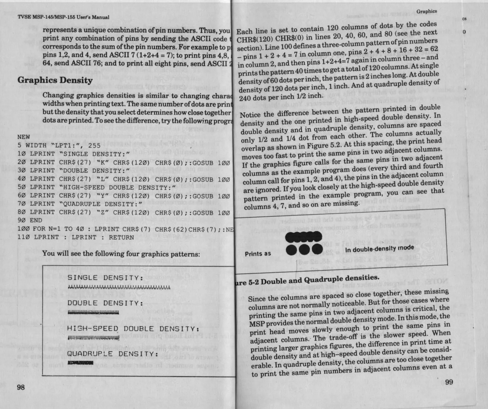
The manual for this printer is a wonder by itself. It is full of sample code in BASIC, contains tables of escape-codes to change formatting and even has a hex-dump mode to help debug programs. This was written at the dawn of computer printing, and so supports both Epson and IBM character code standards. At the end, there’s even a page on timing characteristics and pinouts. They really should make manuals like this nowadays.
The Goal
The eventual goal is to put together a script that takes a color image as input, dithers it, applies various filters to make the output look good and then sends all that to the printer.
First Print
The printer responds to ASCII text sent to it over the parallel port by printing it. Naturally, my first instinct was to run fortune | cowsay > /dev/usb/lp0:
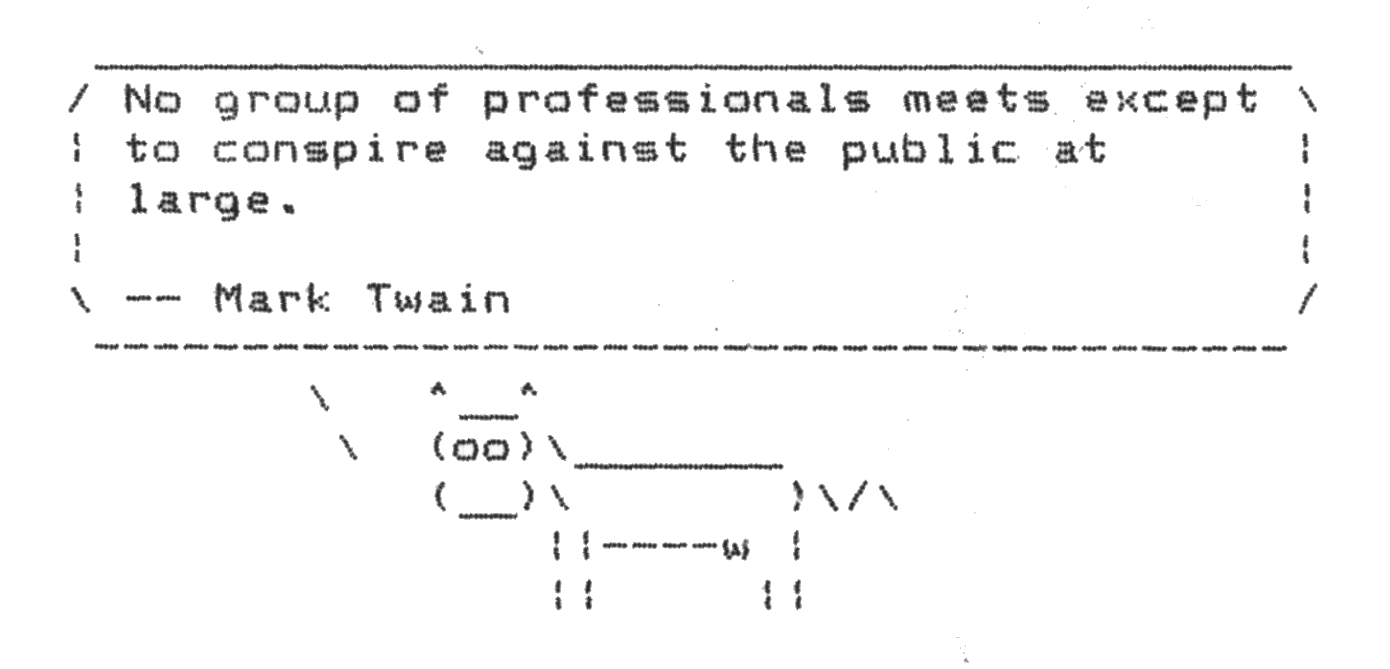
Based on the manual, I quickly threw together some code to convert an input image to the expected format. The printer treats each line as a separate image. We advance the printer’s position in the paper by setting the line-height and sending carriage-return and newline control codes (in that order) after the image.
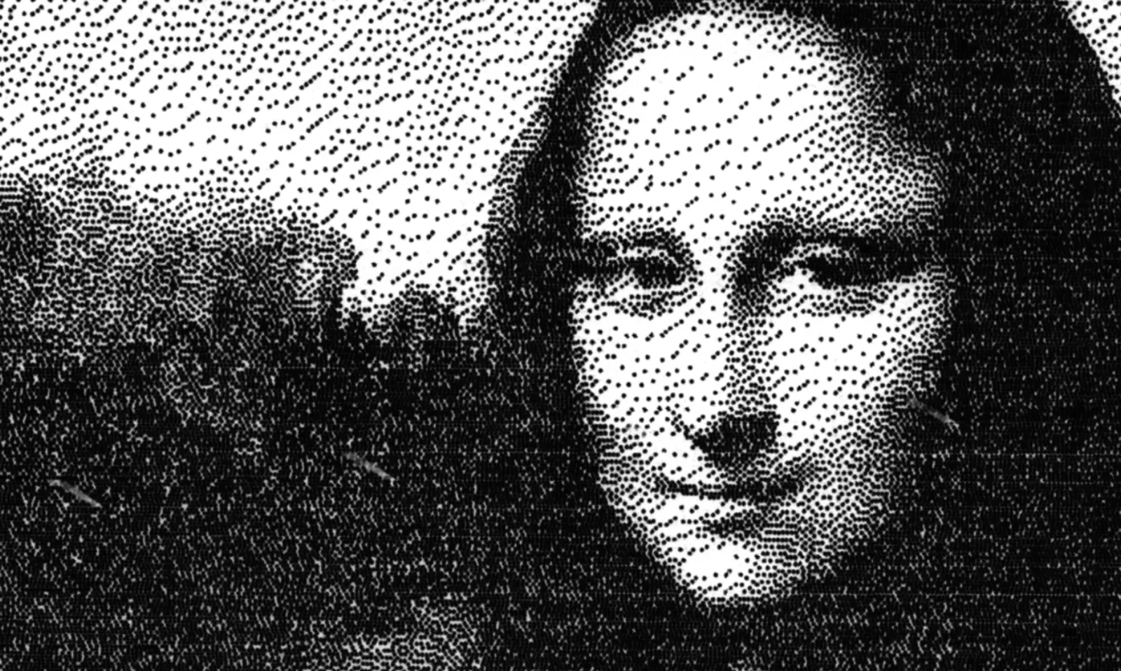
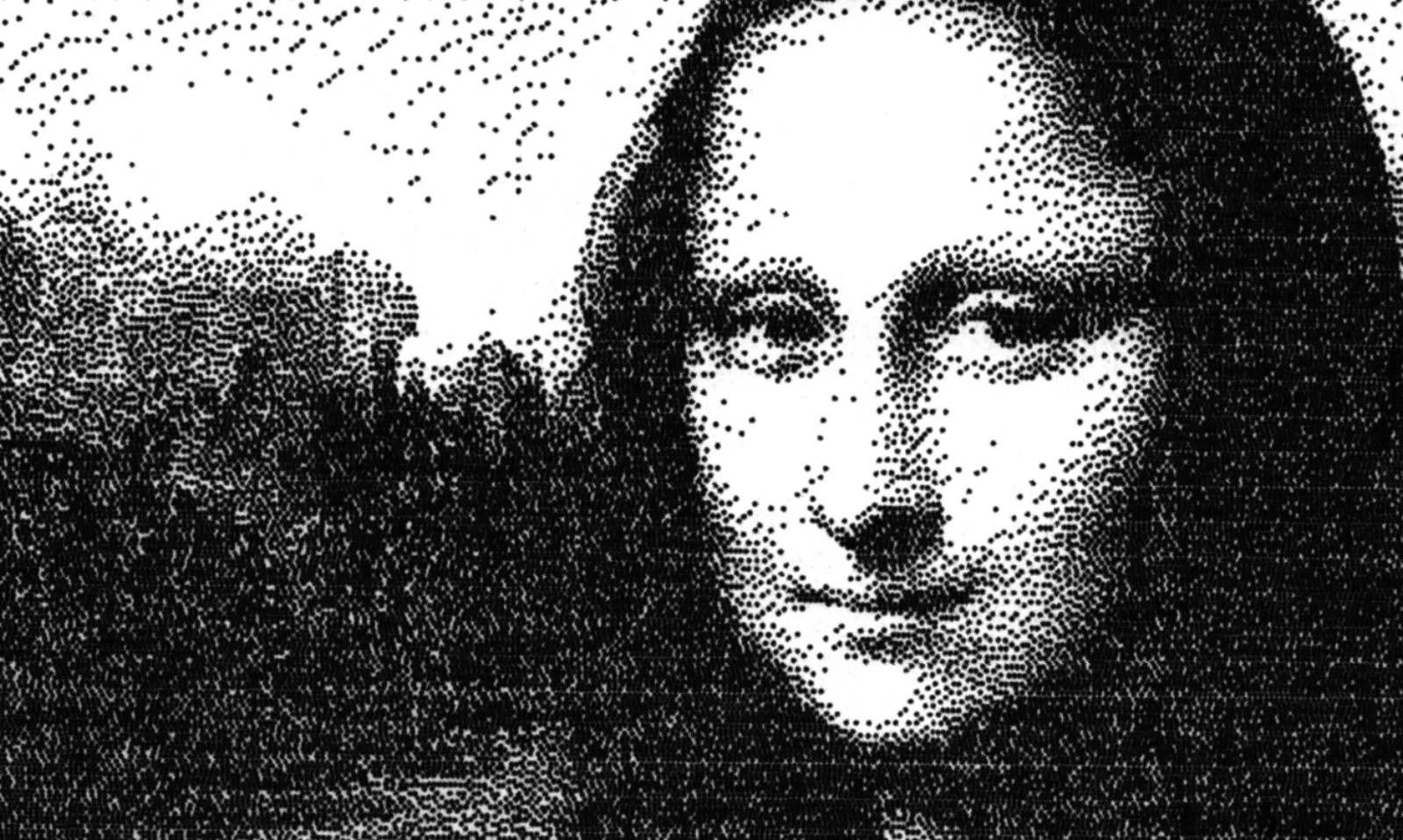
Using Floyd-Steinberg dithering, the test Mona Lisa image looks like this in monochrome:
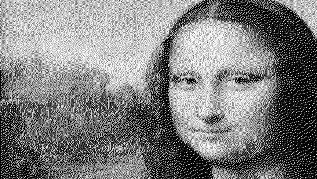
A perfectly recognizable image. When printed, it looks like this:
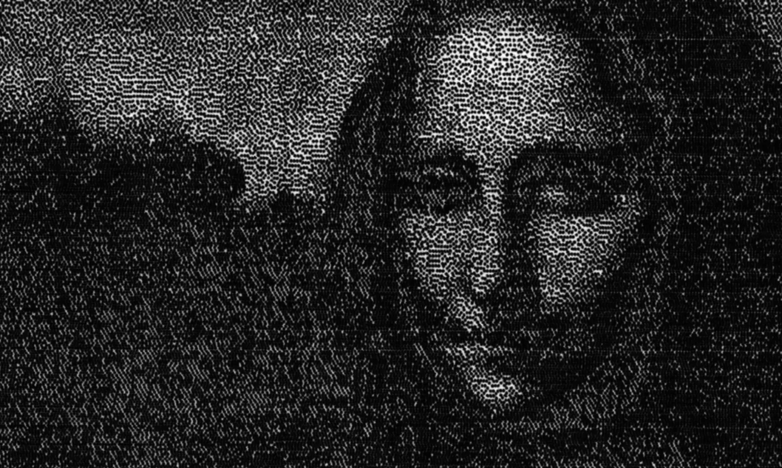
The image is dark, barely recognizable. The classic Floyd-Steinberg dithering patterns dominate the image.
Output and Perception
To fix this, we need to take a look at how the printer sets images down on paper and how we perceive these images. Luckily, the comprehensive manual covers the basics of Dot-Matrix printing.
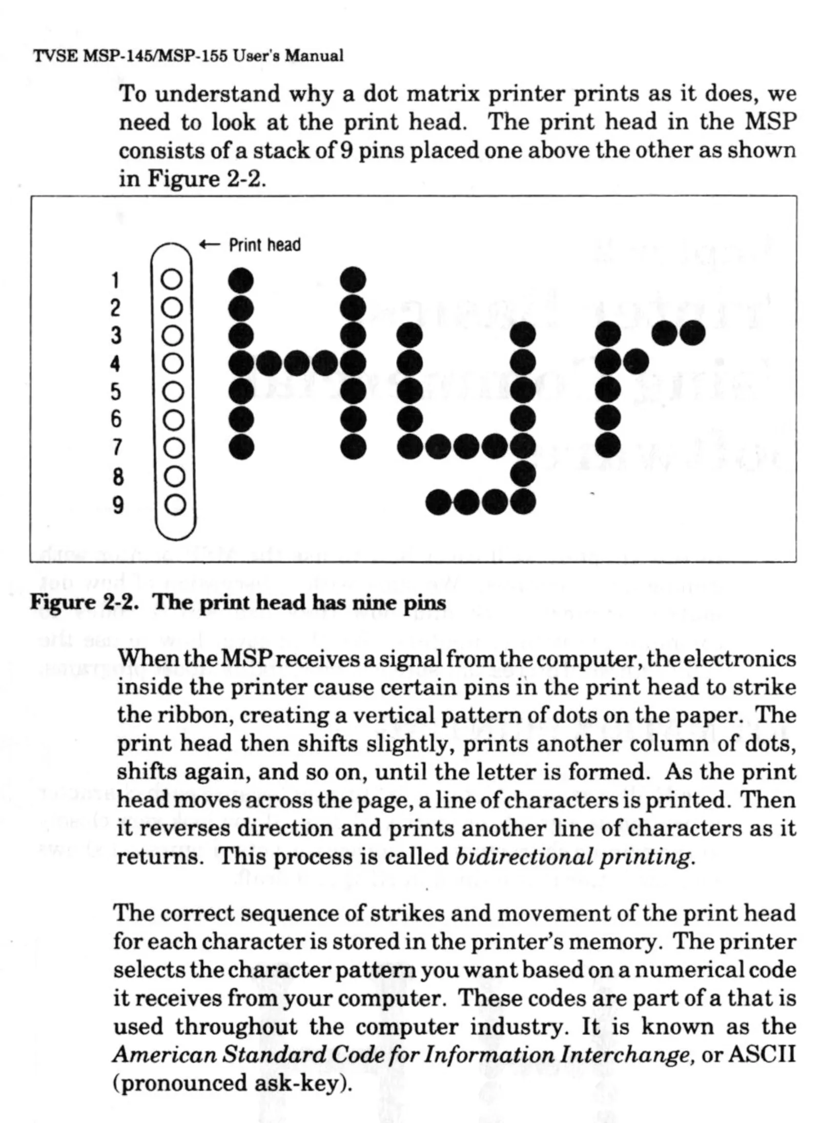
The pitch (or size) of each dot is 1/72” (or one point in PostScript terms). The amount the dots overlap is determined by the graphics density. All images here are rendered at double graphics density, so the space between the center of adjacent dots is half a point. This preserves quality of dark regions and edges.
The fundamental problem here is that of visual impact: on a screen, a dark pixel and a light pixel occupy the same amount of space. They appear similar in size. Through the printer, the area is not divided up into equal-sized cells. Each dot “bleeds” into the adjacent dot areas. This means that the visual impact of a dot is much larger than that of a blank space.
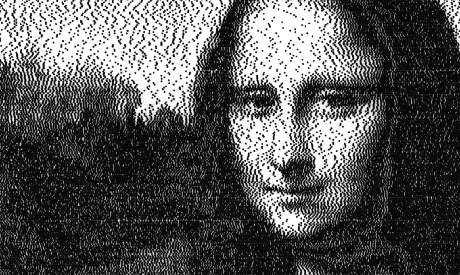
The naive solution to this would be to increase the brightness of the image linearly: for example, we scale each value from the range [0..1] to [0.4..1]. This improves the image:
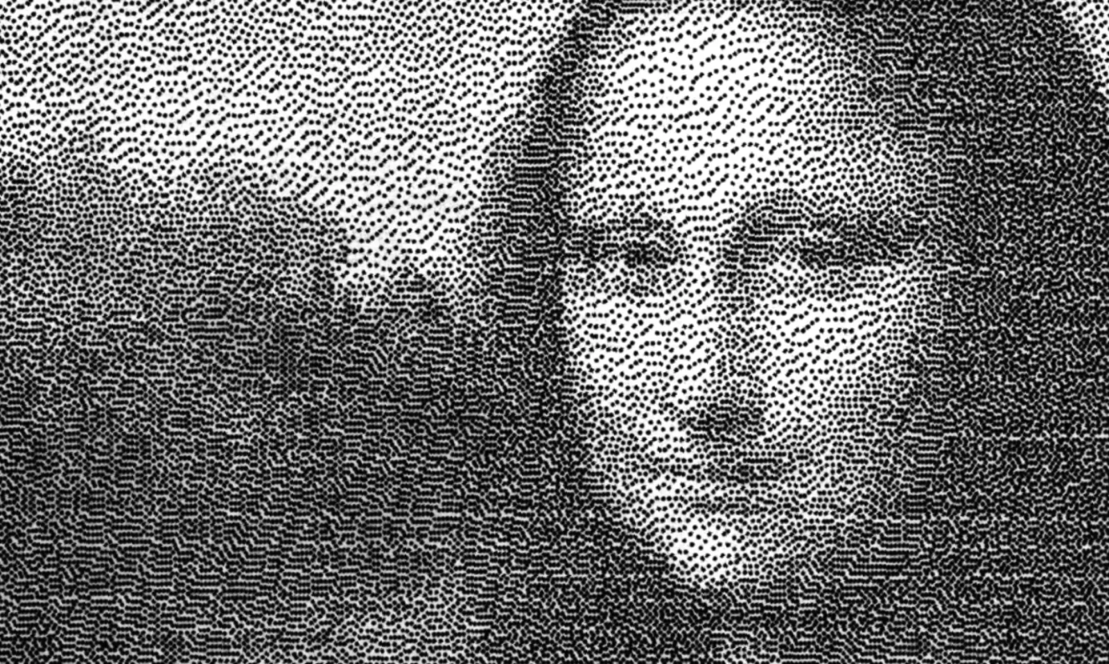
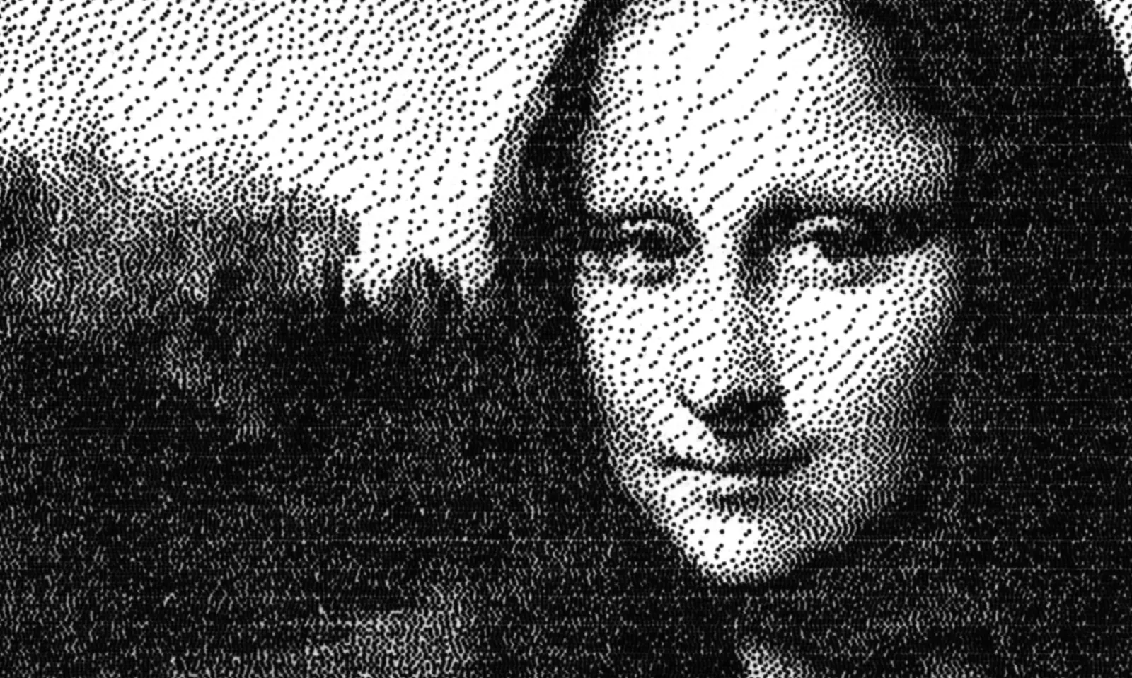
But there is still an issue of contrast. The difference in brightness of the forehead (the brightest part of the image) and the hair (the darkest part) should be greater. So we use a cubic scaling function, a common way to correct contrast in photography.
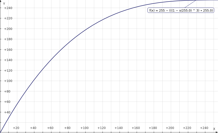
This produces pictures with much better contrast!
Dithering Functions
Now we have a set-up that dithers and draws images automatically. Lets poke around the dithering process and see what happens.
Most dithering algorithms use error diffusion. A simple overview of the common algorithms is available on Tanner Helland’s blog.
Error Function
One of the parameters we can adjust is the fraction of the total error propagated. Atkinson dithering propagates 7/8ths of the error from each cell to the adjacent cells. Because we are not concerned with speed, we do not need to restrict ourselves to binary fractions. Here’s an example where 90% of the error is propagated. As predicted, the white areas of the image are washed out.
The code written allows you to experiment with arbitrary error propagation functions, including probabilistic and piecewise functions for this. That’s a discussion for another time, though.
Error Propagation
Another field we can explore is the way in which this error is shared among surrounding tiles. The Floyd-Steinberg algorithm specifies an error-sharing pattern that generates a checkerboard pattern given an even, grey input image.
Here’s what happens if the error from each pixel is passed to the pixel on its right. The vertical bands are obvious in this image.
The vertical pitch of the printer is 1 point, and the horizontal pitch of the printer is half that. To account for this, we can manipulate the weights assigned. Here’s one possible image when the relative weight assigned to the pixel on the right is increased:
Some banding still exists in this image, but it is far less obvious than in the previous image. The original image (made with Floyd-Steinberg dithering) has no visible banding at all.
Perhaps if I had a mathematical model of the printer’s error function in mind, I could design an error propagation algorithm around that?