This project extends a simple remote-controlled car, allowing it to be controlled by an iPad or by hand gestures. This project builds on the Arduino project, the Kinect and certain HTML5 features (WebSockets, DeviceMotionEvent, Canvas). The final product is this:
Overview
There are two different versions of this project - one for the HTML5 web app, and the other for the Kinect. In the HTML5-based version, the web application uses DeviceMotionEvent to get accelerometer readings and determine what the car has to do. This action is encoded in the format expected by the Arduino sketch, and is then sent over a WebSocket to a simple server written in Python. The Python script simply forwards the received data to the Arduino via the serial port. The Arduino toggles its output to close and open switches on the remote controller (using optical isolators). The car moves correspondingly.
The Kinect-based version functions in a nearly identical manner - the only difference is that the Kinect data is received and processed in the same C# application that dispatches instructions over the serial port. You can download the full source code here.
Now, to take a closer look at each section of this project, from the bottom-up:
The Arduino
The Arduino receives commands from its Serial interface and toggles its output to control the car’s remote controller. For a controller that supports only one speed, the circuit looks like this:
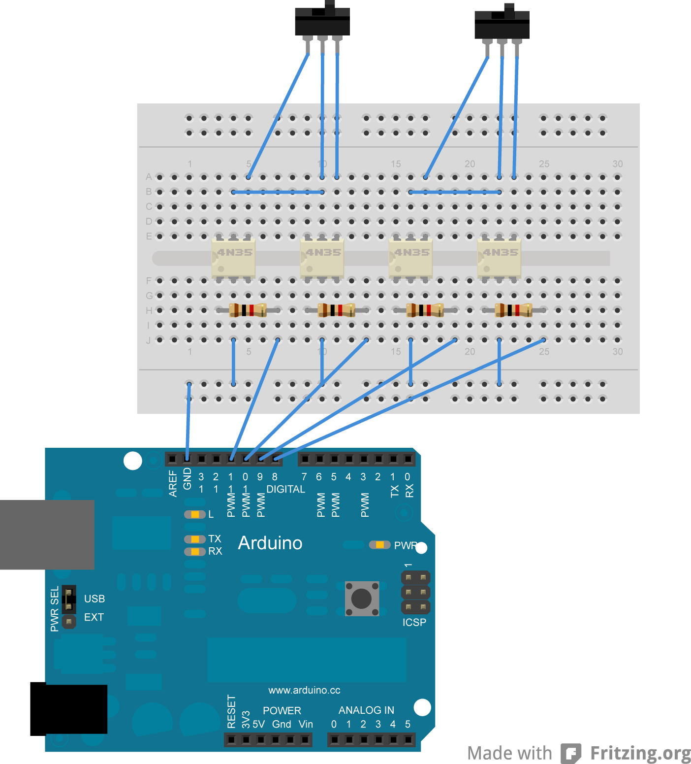
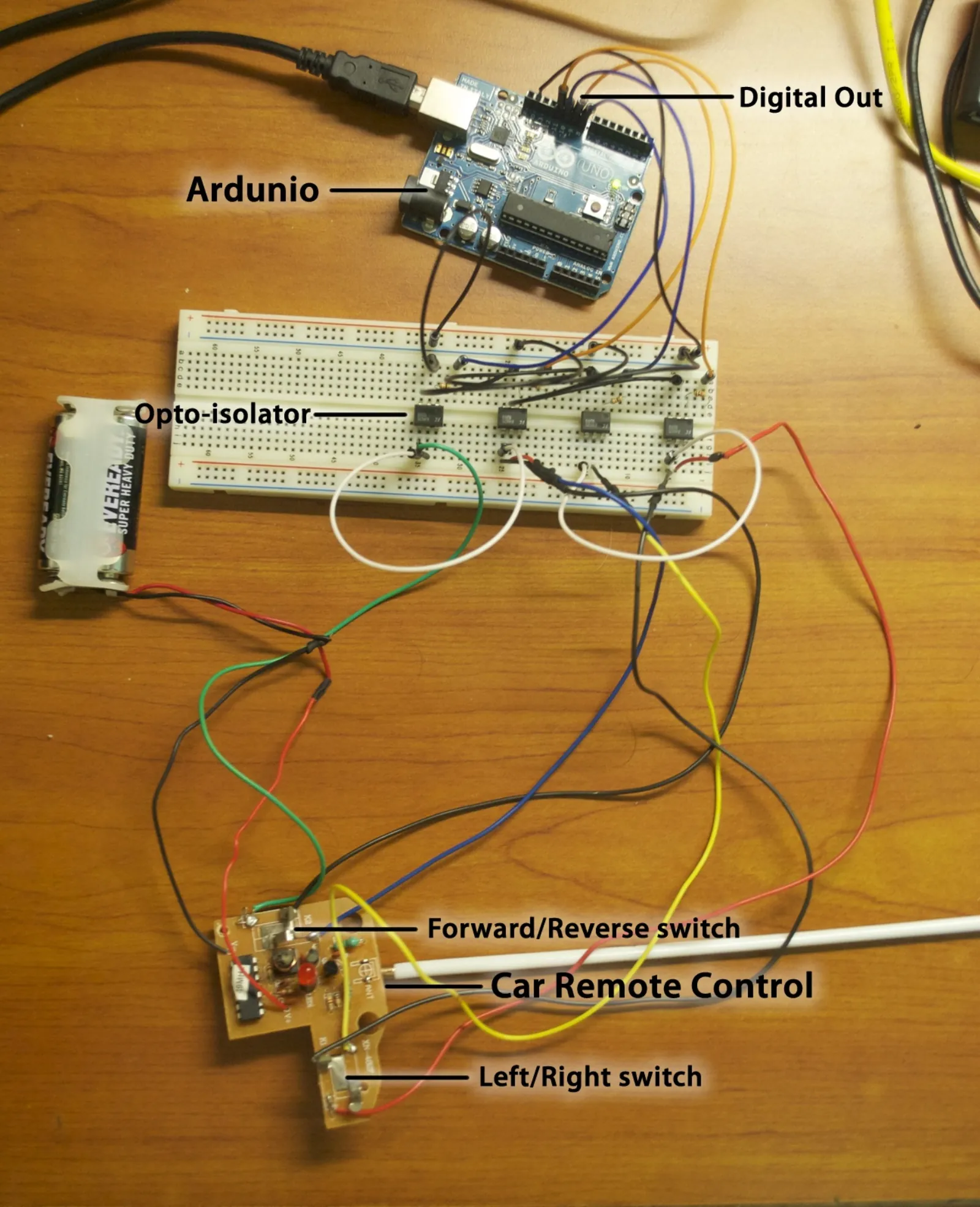
Each output pin controls current passing through an opto-isolator, which isolates the circuit of the Arduino from that of the car’s controller. This allows the Arduino to control the car, despite both circuits having different electrical potentials. The switches at the top of the above diagrams are placeholders for the actual control mechanism of the car. A current-limiting resistor is chosen so as to provide a current within the operating parameters of the opto-isolator. The breadboarded circuit looks like this:
The sketch that the Arduino runs is very simple:
int pinRight = 11;
int pinLeft = 10;
int pinForward = 9;
int pinReverse = 8;
void setup() {
  Serial.begin(9600);
  pinMode(pinRight, OUTPUT);
  pinMode(pinLeft, OUTPUT);
  pinMode(pinForward, OUTPUT);
  pinMode(pinReverse, OUTPUT);
}
void loop() {
  if(Serial.available() > 0){
    int tmpByte = Serial.read();
    switch(tmpByte){
      case 'w': // Move car FORWARDS
        digitalWrite(pinReverse, LOW);
        digitalWrite(pinForward, HIGH);
        break;
      case 's': // Move car in REVERSE
        digitalWrite(pinForward, LOW);
        digitalWrite(pinReverse, HIGH);
        break;
      case 'a': // Turn steering wheels LEFT
        digitalWrite(pinRight, LOW);
        digitalWrite(pinLeft, HIGH);
        break;
      case 'd': // Turn steering wheels RIGHT
        digitalWrite(pinLeft, LOW);
        digitalWrite(pinRight, HIGH);
        break;
      case '_': // STOP ALL motion
        digitalWrite(pinReverse, LOW);
        digitalWrite(pinForward, LOW);
        // The missing break; here is entirely intentional.
      case 'x': // Move steering wheels STRAIGHT
        digitalWrite(pinRight, LOW);
        digitalWrite(pinLeft, LOW);
        break;
      default:
        break;
    }
  }
}
Notice that the digitalWrite(pin, LOW); always precedes the digitalWrite(pin, HIGH); command? This is to prevent conflicting commands from being sent to the car(e.g. Forwards and Backwards simultaneously).
And now, on to the Web App-based controller:
Web Application Controller
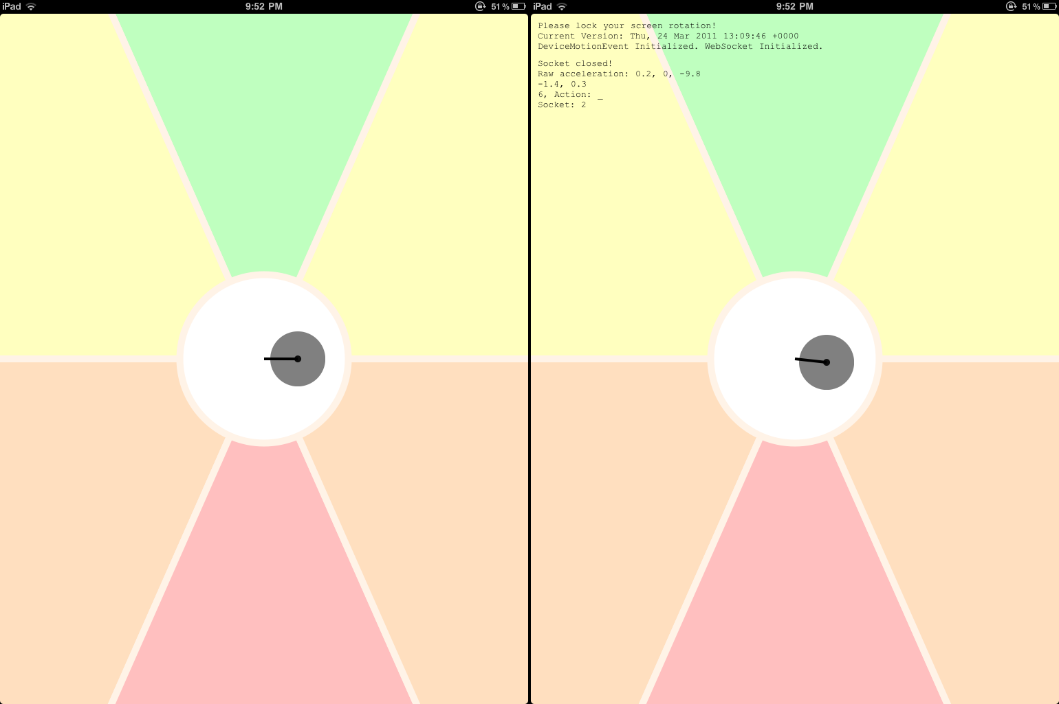
This controller comes in two parts. One is the actual client, which is served as a single html file (with optional additions - discussed later), and one is the server, which is a Python script that simply copies all data sent over a WebSocket to the Arduino over a serial port. This is how the client interface looks like:
The server is based on this Python script (if you want to use a test server, grab this code - the response headers adhere to the Same-Origin Policy). pyserial 2.5 is used to send output to the Arduino.
The web-based client, on the other hand, is much more complex and interesting. A single file (index.html) draws the GUI (using Canvas), reads the tilt angle of the device (using DeviceMotionEvent), calculates the action that the car has to perform and sends the action to the Python script over a WebSocket connection. HTML5 is certainly useful, isn’t it?
The JavaScript has been extensively commented, and is included (along with the optional files) in the download above.
The purpose of the optional files (cache_manifest.php and date.php) is explained in my iPad web app caching post. They are not essential to the functioning of the code.
Kinect Controller
The Kinect controller is written using Code Laboratories’ CL NUI SDK instead of the more commonly used (and official) OpenNI or OpenKinect/libfreenect. The primary motivation in choosing CL NUI over the other SDKs is that CL NUI makes writing code in C# very easy and serial communication is a trivially easy in C#. The tradeoff of writing in managed C# is that (1) Threading is inevitable, which adds to the complexity of the code and (2) The image processing code runs painfully slowly. The software looks like this:
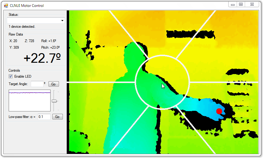
The bar on the left is not relevant to this project - it is just a quick way to move the Kinect up and down (using the built-in motor) and to read and graph the angle over time. The algorithm used to detect the position of the hand has been deliberately kept simple - working with System.Drawing.Bitmap objects is very slow. Here is the algorithm:
// System.Drawing.Bitmap bmpVideoData contains the current frame.
// double xbar, ybar contain the running average of the points that lie
// in the desired depth range. Tweak the incremented values until satisfied
// with the accuracy and speed trade-off. The choice of 10 is arbitrary.
for(int i=0; i < bmpVideoData.Width; i+=10)
    for(int j=0; j < bmpVideoData.Height; j+=10){
        c = bmpVideoData.GetPixel(i, j);
        // Check to see if color of pixel in depth map corresponds to the desired
        // depth range. This was manually calculated beforehand, but can be
        // automated if the range needs to be varied.
        if (c.R == 0 && c.B == 255 && c.G < 192) {
            // Live, numerically stable, mean calculation:
            ++count;
            xbar += (i - xbar) / count; // Update the mean x value
            ybar += (j - ybar) / count; // Update the mean y value
        }
    }
// xbar and ybar will be used to calculate the position of the hand onscreen,
// and the action to be performed by the robot.
As algorithms go, this is among the simplest. It gives surprisingly robust tracking, though. Do note that you need to install Code Laboratories’ CL NUI SDK before you can run the code included in the download above. Once you have done that, copy CLNUIDevice.cs, CLNUIDevice.dll and NUIImage.cs into the project folder, replacing the existing files. (As per their SDK license requirements, I cannot distribute these files directly).
Future Expansion
- Use the Ethernet shield and write a sketch that allows the Arduino to act as a WebSocket server. This will remove the need for having a computer as an intermediary (to forward WebSocket data to the Arduino over the serial port).
- Modify the web app code to automatically use the internal gyroscope when available (by using DeviceOrientationEvent instead of DeviceMotionEvent). When I eventually get a device with a gyroscope, I’ll look into it.
- Implement the same thing in a toy helicopter. Same concept, new dimension! Use the Kinect to gather positional data, and the iPad to steer it around.
- Modify the vision algorithm to detect each hand separately (using a conditional floodfill), and allow each hand to control a different car. Alternatively, use it to steer a helicopter in three dimensions.