As part of my various keyboard projects I have been working on PCBs in KiCAD. KiCAD is fantastic, and I love the hierarchical sheets feature which allows you to organize your schematic into a tree of sheets. This is great for keyboards, which have a lot of repeated components around each key, and it also allows you to organize your schematic into logical blocks.
However, the hierarchical sheets are not reflected in the PCB layout. This means that I would have to manually lay out the debounce circuit and the LEDs around each and every key in the keyboard. Since the Zeeland I and the AngloDox both have a lot of keys, this would be an enormous pain. What I needed was a method of abstraction for PCB layout similar to the hierarchical sheets in the schematic.
There are two current ways to do this: PCB rooms in Altium Designer, and the ReplicateLayout plugin for KiCAD. The former costs an arm and a leg, and only supports a single level of abstraction – anathema to a programmer. The latter is a plugin for KiCAD that allows you to copy and paste a layout, but –again– it is limited to a single layer of abstraction, its interface requires too much cognitive overhead, and has some weird problems with copied traces.
Naturally, this was the cue for me to throw my own hat into the ring with the HierarchicalPCB plugin. If you want to see how its useful, check out the AngloDox keyboard. At time of writing this isn’t complete, but it is a great illustration of what it can do.
The HierarchicalPCB plugin
I decided to write a plugin to automate this process. Its open source and available on my GitHub and eventually on the KiCAD plugin repository. Here’s how the plugin works:
Let’s say you have a hierarchical schematic for a keyboard with three levels of abstraction: PCB.kicad_sch ⇒ key_module.kicad_sch ⇒ key.kicad_sch. Each individual keyswitch, its debouncing circuit, and its LED are specified in key.kicad_sch. Sets of eight keys are arranged in a bank in key_module.kicad_sch all connected to a shift register. Finally, these banks are connected in series in PCB.kicad_sch along with a microcontroller and ancillary circuits.
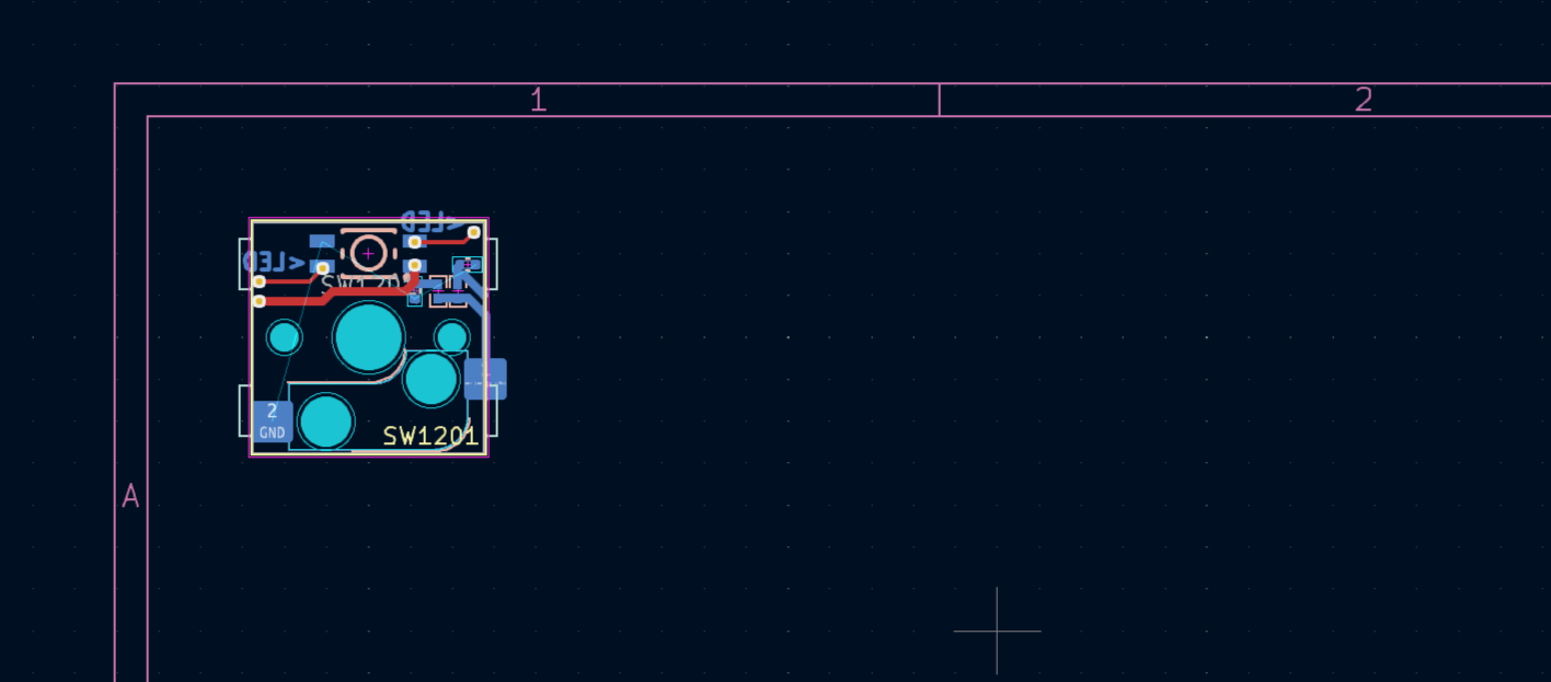
To use this plugin, we create a key.kicad_pcb alongside the key.kicad_sch. This is a template PCB that contains the layout of the key, the debouncing circuit, and the LED. We wish to design these once and propagate the layout everywhere. Here’s the layout defined in key.kicad_pcb:
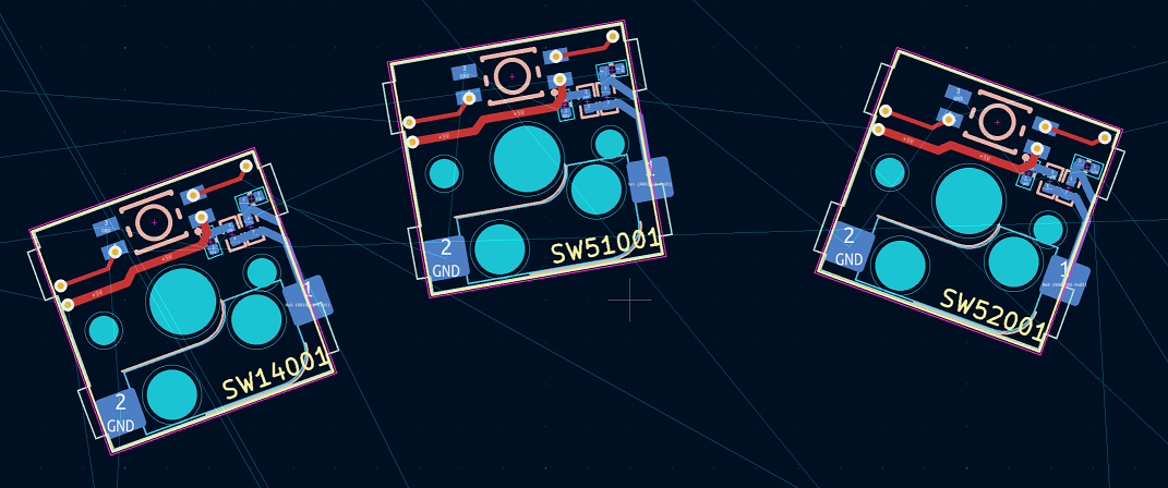
We switch to PCB.kicad_pcb and lay the keys out in the desired positions and orientations (potentially using another one of my plugins), and then we run the plugin. It propagates the layout to the switches:
And the best part? You can make a change to the template PCB and re-run the plugin, and it will propagate the changes to all the instances.
Take a look at the documentation for a more thorough description of how to use it.