
The Taig mill comes with a manual switch to turn the motor on and off. This is pretty annoying, I’d like to be able to hit “Cycle Start” and have that happen automatically. Here’s a quick and inexpensive way to turn the motor on and off.
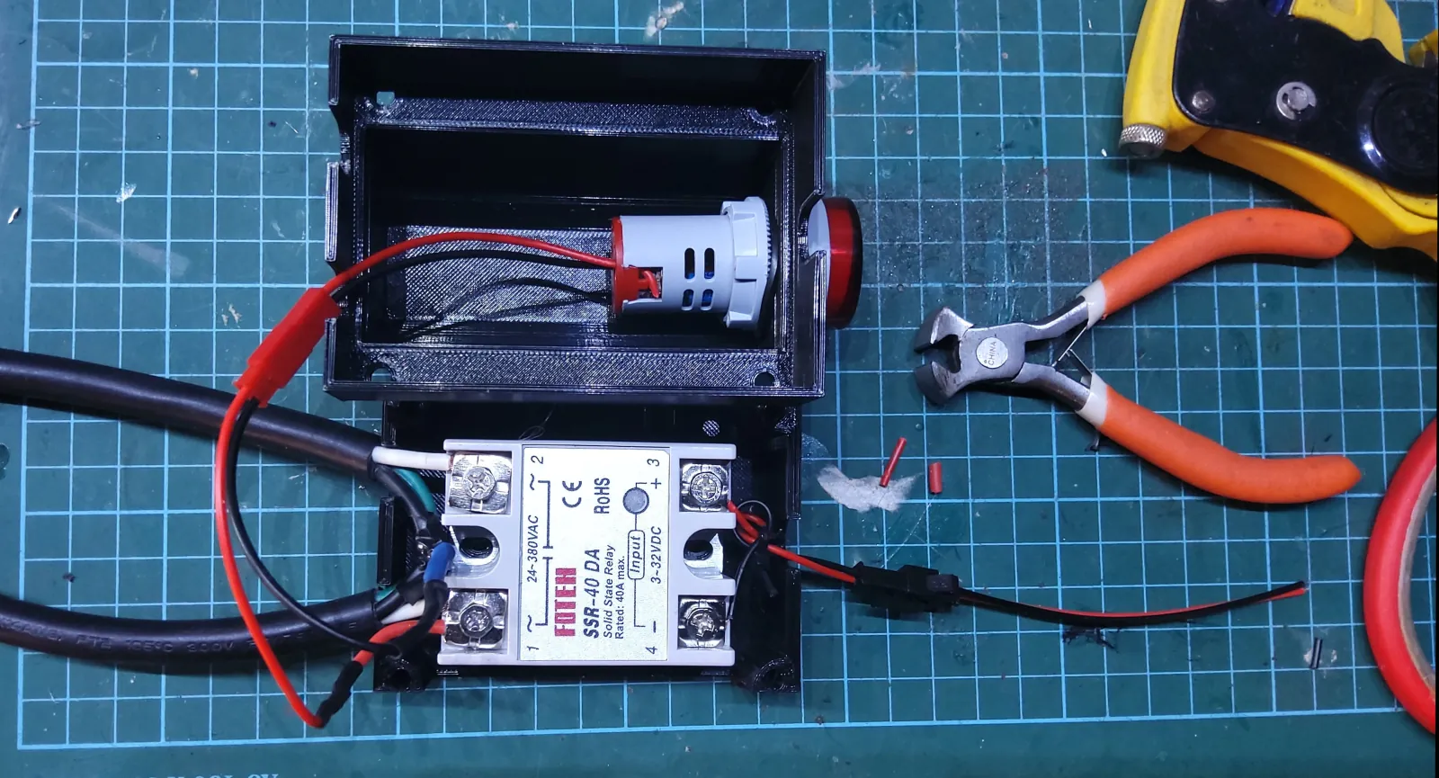
The idea is to modify an extension cable to add a solid-state relay. An additional AC voltmeter lights up when AC power is available (to show that the motor may turn on based on external input). All this is wired into a small 3d-printed case which can be zip-tied or screwed to the case.
Modifying a C14 to C13 power cord lets us make this component modular. It can easily be introduced between the power switch (which is now used as a safety override), and the motor itself.
See the Taig mill planning post for the full bill of materials.
Detachable Probing
Here’s an interesting problem: the mill has a tool-setter and a touch probe which both have to connect to a single probe input on the controller. The tool-setter will always be connected, but the touch probe has to be detachable without affecting the tool-setter. Both sensors are normally-closed and break the circuit when triggered.
Connecting multiple inputs in series would be the usual way to trip the probe when either is triggered. The problem here is the requirement that the touch probe be removable: if we just remove the touch probe, we won’t be able to use the tool-setter by itself.
Our requirements are:
- If the probe is not connected, the
PROBEpin must be triggered if:- the tool-setter is triggered, or
- in a fault condition.
- If the probe is connected, the
PROBEpin must be triggered if:- the tool-setter is triggered, or
- the removable probe is triggered, or
- either is in a fault condition.
For safety reasons we can’t just switch to a normally-open circuit and wire them up in parallel.
The solution I went with is to use a circuit that uses a transistor to short the probe pins when the probe is removed. The trick is to short a wire in one of the connectors to ground and use it (along with a board-mounted pull-up resistor) to disable a transistor. The circuit diagram is here:

The component in the middle is an opto-isolator, chosen because I had some handy. A transistor would work just as well.
The circuit was made on a simple breakout board, with 3-pin DX-16 connectors between the controller and the first module, and 5-pin connectors between the breakout board and the tool-setter and the removable probe. To prevent accidentally shorting the 5V rail to ground, each 5-pin connector uses a separate pin for 5V and SENSE.